Continuando con el howto, ya solo queda instalar los espejos autopolarizables. Antes de continuar, voy a aclarar que esto es un oscurecido del espejo automático, para evitar se deslumbrado por las luces de vehículos que tenemos detrás. Lo aclaro por que muchos me han dicho «No lo veo util, total, el sol no deslumbra tanto». También hay que tener en cuenta que solo se activa de noche, y que hay que tener el sistema de luces automáticas.
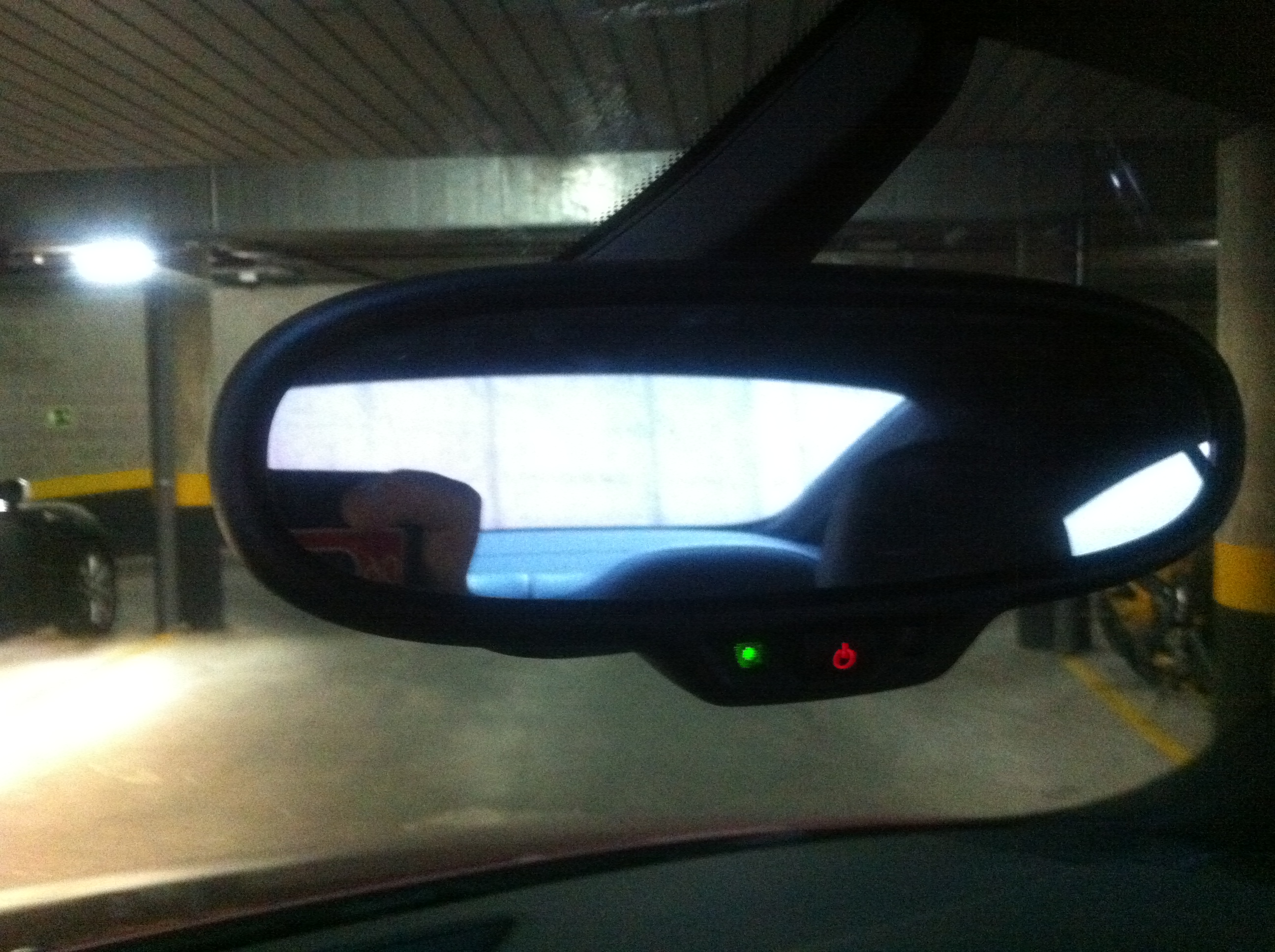
Tengo que aclarar que mi TT ya vino de fabrica con el espejo central antideslumbrante, si lo teneis que instalar hay un montón de howtos para hacerlo, pero tener en cuenta que si vuestro espejo no tiene detección de luz y lluvia, será necesario ponerlo, y para estoy hay que cambiar la luna.
Pongo unas fotos para que se vea el efecto del oscurecido:
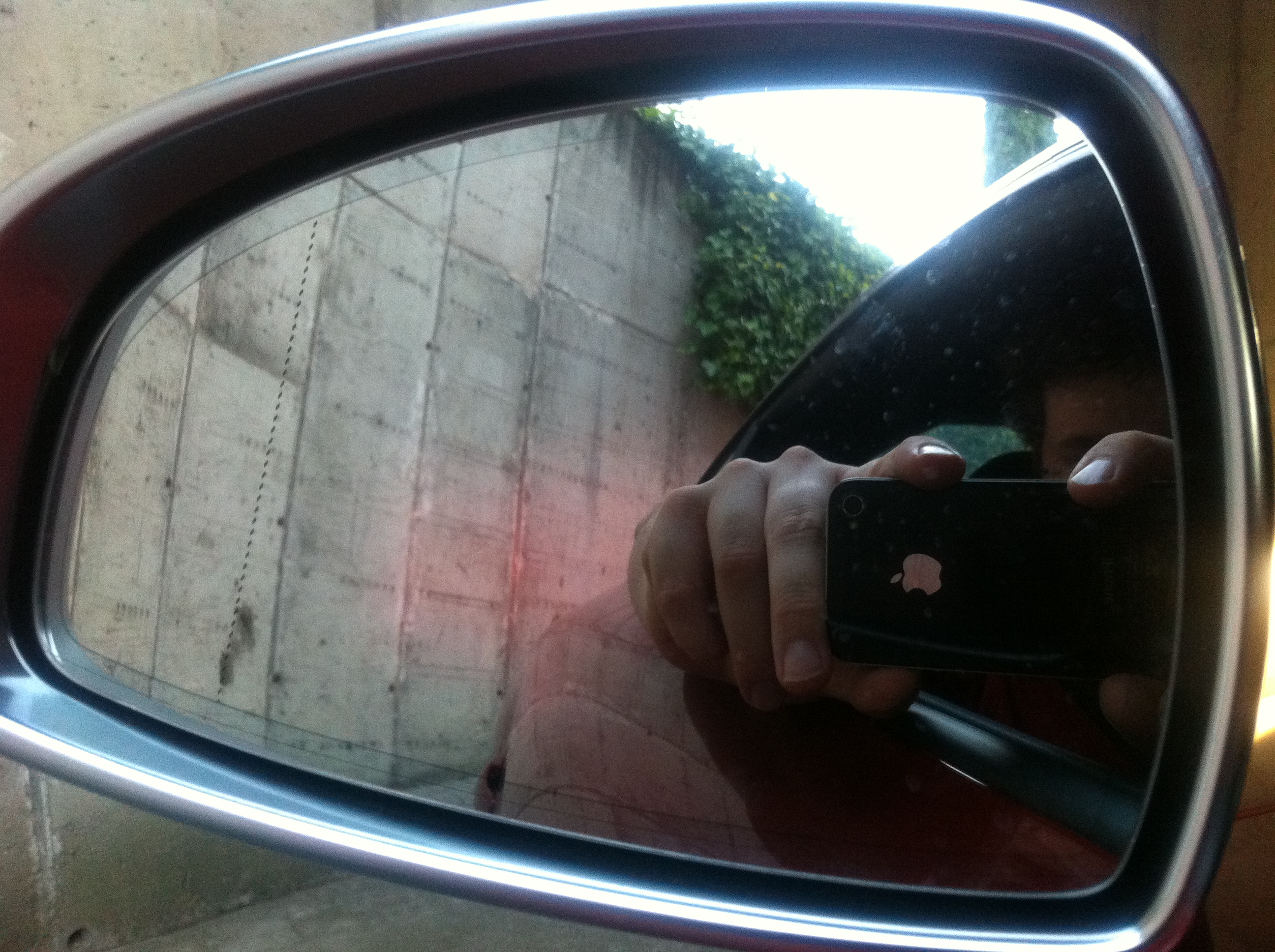
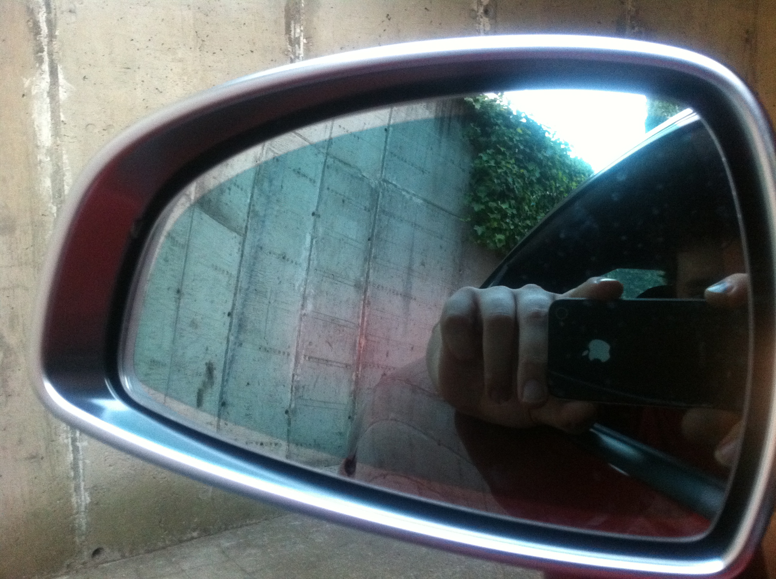
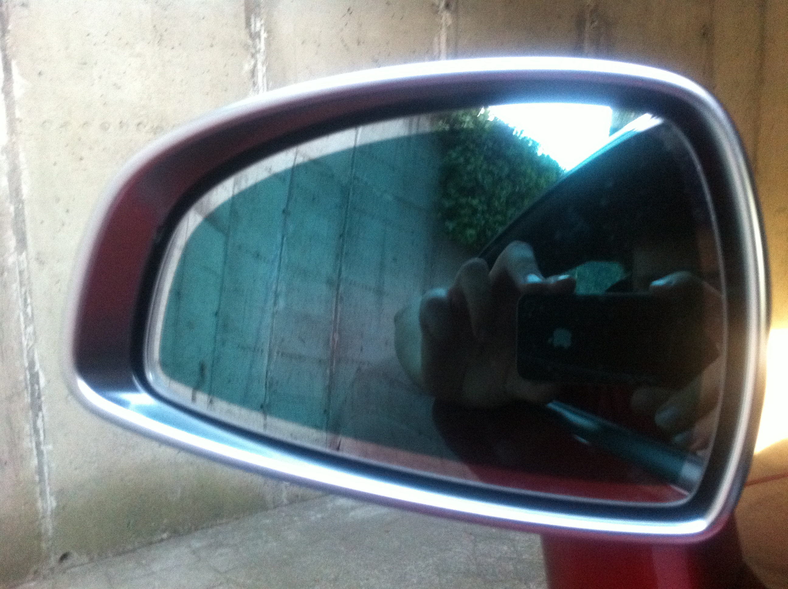
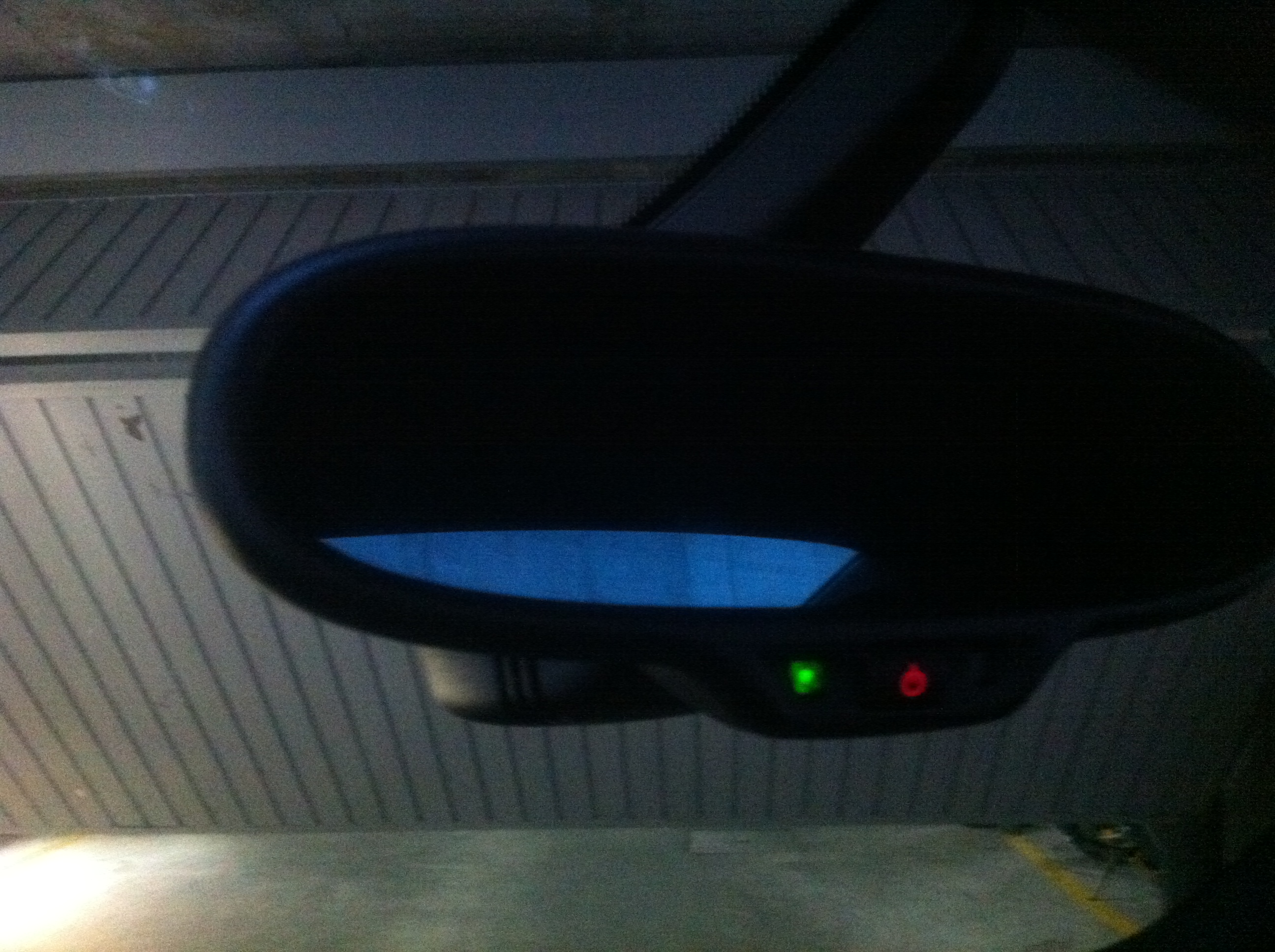
Como podeis observar, el oscurecido es gradual según el grado de luz que recibe el espejo central, que es quien controla los tres espejos.
La instalación no es complicada, pero si laboriosa, en la instalación original el cable va en el mazo principal del coche, bajando por el pilar delantero izquierdo hasta el salpicadero y de ahí hasta las dos centralitas de las puertas. Nosotros no lo vamos a hacer así ya que no es nada recomendable desmontar el salpicadero del coche; bajaremos los cables por el pilar del conductor hasta su puerta, y por el pilar del pasajero hasta su puerta.
Solo es necesario cablear desde el pin 4 y 5 del conector del espejo hasta cada una de las dos puertas, no pasa por centralita, ni nada similar.
El pinout de las centralitas de las puertas es el siguiente:
Following the DIY, i am just installing the anti dazzle wing mirrors to avoid being dazzled by the headlights of vehicles behind us. Also keep in mind that only active at night (it will no work with sun light), and you have to have the automatic light system.
I bought the tt with anti glare central mirror which is needed by the anti dazzle wing mirrors, if you have to install there are plenty of DIY, but bear in mind that if your mirror has no light detection and rain, you will need to put it and that means to change the cristal.
Some photos you can see the effect:
As you can see, the dark is gradual as the degree of light reaching the central mirror, which is who controls the three mirrors.
Installation is not complicated, in the original installation the cable goes on the main deck of the car, down the left front pillar to the dash and on to the two exchanges of the doors. We are not going to do well because it is not advisable to remove the dashboard of your car, go down the wires through the pillar of the driver to driver door, and the pillar of the passenger to passenger door.
Just need to wire from pin 4 and 5 of the connector of the central mirror to each of the two doors.
Here is the pinout of the control units of the doors:
20-pin connector (supply, lock)
1 – Mirror dip input signal 1 (EC mirror +)
2 – CL motor SAFE
3 – CL feedback locked/safe
4 – CL outside door handle
5- Vacant
6- Vacant
7 – CL terminal 31
8 – CAN – High
9 – CAN – Low
10 – Mirror dip input signal 2 (EC mirror -)
11 – CL motor SAFE/lock
12 – CL terminal 30
13 – CL keyswitch close/open
14- Vacant
15 – CL door contact switch
16 – CL motor unlock
17- Vacant
18 – WL enable, terminal 87 (vacant)
19 – WL terminal 31
20 – WL terminal 30
16-pin connector (exterior mirrors)
1 – Mirror status position X (only with seat memory fitted)
2 – Mirror terminal 31, potentiometer (only with seat memory fitted)
3 – Mirror supply, potentiometer (only with seat memory fitted)
4 – Mirror adjustment motor Y-direction
5 – Mirror adjustment motor X/Y-direction
6- Vacant
7 – Mirror heating
8 – Mirror dip output signal 1 (EC mirror +)
9 – Mirror status position Y (only with seat memory fitted)
10- Vacant
11 – Mirror terminal 31
12 – Mirror adjustment motor X-direction
13- Vacant
14 – Mirror folding motor –
15 – Mirror folding motor +
16 – Mirror dip output signal 2 (EC mirror -)
32-pin connector (to door trim)
1 – BE – Exit/warning lamp
2 – BE – Terminal 31 (2) (AWL)
3 – BF – Window lifter button rear right
4 – BE – Terminal 31 (1) (AWL)
5 – CL SAFE LED
6 – BE – Terminal 58b (1)
7 – BF – Interior locking button (LOCK/UNLOCK)
8 – BF – Window lifter button front right (local)
9- Vacant
10 – Memory button + emergency off button (only with seat memory fitted)
11 – Memory position buttons (only with seat memory fitted)
12 – BF – Tailgate remote release button (only in 5-door, USA)
13 – Alarm system Off button (tilt sensor inactive)
14 – BE – Interior door handle illumination
15- Vacant
16 – Status LED button for interior monitoring (deactivate interior monitoring)
17 – Status LED button for alarm system off (deactivate tilt sensor)
18 – CL – Inside door handle (not implemented)
19 – BF – Mirror adjustment L/R
20 – BF – Mirror adjustment X/Y
21 – BF – Window lifter button rear right (local)
22 – BE – Terminal 58b (2) (mirror adjuster switch)
23 – BE – Terminal 58b (3) (mirror/stowage illumination)
24 – BF – Window lifter button front left (local)
25- Vacant
26 – BF – Child lock
27 – Memory supply terminal 30
28 – BF – Button for tank lid unlock
29 – BF – Mirror heating
30 – Button for interior monitoring
31 – LED – Interior locking button (LOCK)
32 – LED – Child lock button
Como podeis ver hay que conectar el cable 4 del espejo al terminal 1 del conector de la puerta, y el terminal 5 al pin 10. Para hacerlo lo más cómodo es desmontar el techo, ya que hay que andar colocando cables con cinta por este, y sin sacar el guarnecido va a ser casi simposible, con lo que necesitaremos sacar el revestimineto de los dos pilares A, el techo al completo, y por la parte de abajo del coche, será necesario también quitar los guarnecidos que cubren los pasos de puerta (justo al lado de los asientos.) para así poder sacar las piezas plasticas que quedan delante de los mismos, y que es necesario sacar para poder acceder al conector de cableado de la puerta.
Por suerte no hay que programar nada con vagcom, solo instalar el cableado que no es poco.
20-pin connector (supply, lock)
1 – Mirror dip input signal 1 (EC mirror +)
2 – CL motor SAFE
3 – CL feedback locked/safe
4 – CL outside door handle
5- Vacant
6- Vacant
7 – CL terminal 31
8 – CAN – High
9 – CAN – Low
10 – Mirror dip input signal 2 (EC mirror -)
11 – CL motor SAFE/lock
12 – CL terminal 30
13 – CL keyswitch close/open
14- Vacant
15 – CL door contact switch
16 – CL motor unlock
17- Vacant
18 – WL enable, terminal 87 (vacant)
19 – WL terminal 31
20 – WL terminal 30
16-pin connector (exterior mirrors)
1 – Mirror status position X (only with seat memory fitted)
2 – Mirror terminal 31, potentiometer (only with seat memory fitted)
3 – Mirror supply, potentiometer (only with seat memory fitted)
4 – Mirror adjustment motor Y-direction
5 – Mirror adjustment motor X/Y-direction
6- Vacant
7 – Mirror heating
8 – Mirror dip output signal 1 (EC mirror +)
9 – Mirror status position Y (only with seat memory fitted)
10- Vacant
11 – Mirror terminal 31
12 – Mirror adjustment motor X-direction
13- Vacant
14 – Mirror folding motor –
15 – Mirror folding motor +
16 – Mirror dip output signal 2 (EC mirror -)
32-pin connector (to door trim)
1 – BE – Exit/warning lamp
2 – BE – Terminal 31 (2) (AWL)
3 – BF – Window lifter button rear right
4 – BE – Terminal 31 (1) (AWL)
5 – CL SAFE LED
6 – BE – Terminal 58b (1)
7 – BF – Interior locking button (LOCK/UNLOCK)
8 – BF – Window lifter button front right (local)
9- Vacant
10 – Memory button + emergency off button (only with seat memory fitted)
11 – Memory position buttons (only with seat memory fitted)
12 – BF – Tailgate remote release button (only in 5-door, USA)
13 – Alarm system Off button (tilt sensor inactive)
14 – BE – Interior door handle illumination
15- Vacant
16 – Status LED button for interior monitoring (deactivate interior monitoring)
17 – Status LED button for alarm system off (deactivate tilt sensor)
18 – CL – Inside door handle (not implemented)
19 – BF – Mirror adjustment L/R
20 – BF – Mirror adjustment X/Y
21 – BF – Window lifter button rear right (local)
22 – BE – Terminal 58b (2) (mirror adjuster switch)
23 – BE – Terminal 58b (3) (mirror/stowage illumination)
24 – BF – Window lifter button front left (local)
25- Vacant
26 – BF – Child lock
27 – Memory supply terminal 30
28 – BF – Button for tank lid unlock
29 – BF – Mirror heating
30 – Button for interior monitoring
31 – LED – Interior locking button (LOCK)
32 – LED – Child lock button
The cable must be connected from central mirror pin 4 to door drive pin 1, and central mirror pin 5 to door drive pin 10.
Luckily no vagcom to program anything, just install the wiring that is not small.
Do you have any other links or details on this setup? Did you also add the motorized mirror bases for the folding, or did you only add anti-dazzle?
My car came with the center mirror as anti-dazzle, I would like to retrofit the side mirrors though. I don’t care about the folding (it would be nice to have it was easy and cheap to add).
Hi there !
I did retrofit anti glare, and self folding mirrors, here the DIY:
http://blog.alvarolopez.net/2012/07/como-instalar-espejos-plegables-electricamente-calefactados-y-autopolarizables-en-audi-tt-8j-mk2-parte-i/
sorry, it’s only in spanish, use google translator !
Hola Alvaro,
Te sigo tambien en el foro del club TT.. Pedazo trabajo que te pegaste en su dia.. yo ahora voy a hacer el pack completo ya que llevo el retrovisor interior anti deslumbramiento aprovecho.
Solo tengo una duda.. es necesario comprar algun espejo especifico para que se oscurezcan??
Muchas gracias por el tutorial!!
Marco
Gracias por tu comenario !
Si, es necesario comprar los espejos antireflectantes, siento no tener la referencia, pero en ebay los puedes encontrar buscando por «anti glare side mirror»
un saludo
Álvaro